Err

OrigaFlex - The flexible Bipotentiostat

(Code: BIPOTOrigaFlex)


The versatil Bipotentiostat:

Mode details on how it works

0g

THE BIPOTENTIOSTAT MODE WITH ORIGAFLEX POTENTIOSTATS


hOW IT WORKS
Combinations
Electrode connections
PC Software
Testimony
How it works

Each potentiostat of the OrigaFlex range can be used as a Bipotentiostat. To do so, it is necessary to connect three OrigaFlex devices. On one potentiostat, you connect a working electrode. On the second one, you connect the second working electrode. And finally, on the third one, you connect the counter-electrode, the reference electrode (if you work with three electrodes) and a second reference electrode (if you work with 4 electrodes). 

DRIVE UNIT

The Drive Unit & Dummy Cell remains mandatory at any case. It supplies power to all the channels and monitors all the potentiostats together, thanks to an Ethernet connection.

WRK 1 AND REF 2

The Potentiostat n°1:

The working electrode n°1 for a configuration in 2, 3 or 4 electrodes.

WRK 2 AND REF 2

The Potentiostat n°2:

The working electrode n°2 for a configuration in 2, 3 or 4 electrodes.

AUX AND REF

The Potentiostat n°3 :

The counter-electrode

The reference electrode

The combinations

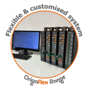
The OrigaFlex range is a trully multi-Potentiostats system. It allows you to combine the powers:

500 mA, 1A, 5A and 10A.

The best combinations

In order to work in the best conditions with the OrigaFlex Bipotentiostat configuration, you may follow the below equation:

Current WRK 1 + Current WRK 2 < Current AUX

1. OGF500 + OGF500 + OGF01A

2. OGF500 + OGF500 + OGF05A

3. OGF500 + OGF01A + OGF05A

4. OGF01A + OGF01A + OGF05A

5. OGF500 + OGF500 + OGF10A

6. OGF500 + OGF01A + OGF10A

7. OGF500 + OGF05A + OGF10A

8. OGF01A + OGF01A + OGF10A

9. OGF01A + OGF05A + OGF10A

The other combinations

All the combinations remain available, all depending on the level of current you work with. Example: if the current does not exceed 200 mA per channel, you can easily use thee OGF500 : 200 + 200 < 500.

10. OGF500 + OGF500 + OGF500

11. OGF01A + OGF01A + OGF01A

12. OGF05A + OGF05A + OGF05A

13. OGF500 + OGF01A + OGF01A

14. OGF500 + OGF10A + OGF10A

15. OGF01A + OGF10A + OGF10A

16. OGF05A + OGF05A + OGF10A

17. OGF05A + OGF10A + OGF10A

18. OGF10A + OGF10A + OGF10A

Electrode connections

The electrodes are connected as below, according to the needed configuration.

2 electrodes: Two working electrodes and one counter-electrode.  

3 electrodes: Two working electrodes, one counter-electrode and one reference electrode (see the draw below).

4 electrodes: Two working electrodes, one counter-electrode and three reference electrodes (see other connections in dotted lines).

At any case, connect the three "Batteries" sockets ach other, with a the dedicated cable.

Connection cable between the channels

This cable links the following connectors:

  • The REF of the 3 channels
  • The AUX of the 3 channels
  • The Ref and the AUX of the channel n°3

The "Battery" plug is a parallel connector. Indeed, it includes the connectors WRK, AUX, REF and REF 2.

Example: three OrigaFlex - OGF500

PC Software: OrigaViewer 2

The software allows you to control a multi-channel system. To proceed, just load the sequences on each potentiostat/galvanostat channel and run it, simultaneously, from the PC Software. Each channel remains independant. For instance: stopping only one channel is possible, the others are still running.

Moreover, OrigaViewer is protected by an ID and Password.

The curves are displayed on real time and then you can anlyze it with OrigaMaster (the PC Software used with single channel to create sequences). It can be exportable to Excel, Open office...

Concretly, see below the electrode configuration you need to set on the software to get a bipotentiostat mode:

WRK 1 and REF 2

Into OrigaMaster 5, select in the START block, the following configuration:

  • "3 electrodes" if you work in 3 electrodes mode.
  • "4 electrodes" if you work in 4 electrodes mode.

WRK 2 and REF 2

Into OrigaMaster 5, select in the START block, the following configuration:

  • "3 electrodes" if you work in 3 electrodes mode.
  • "4 electrodes" if you work in 4 electrodes mode.

AUX and REF

Into OrigaMaster 5, select in the START block, the following configuration:

  • "4 electrodes inverted" if you work in 2, 3 or 4 electrodes mode.

POTENTIOSTAT 1

OrigaMaster 5, START block set-up

POTENTIOSTAT 2

OrigaMaster 5, START block set-up

POTENTIOSTAT 3

OrigaMaster 5, START block set-up

Georg-August-Universität Göttingen Testimony


Do you need more information? Contact us by phone +33 9 54 17 56 03 or by filling the formula

 
Newsletter OrigaLys
last updates and special offers
Subscribe to our newsletter.

secured payment
100% Secured Payment
Check our different payment methods
fast delivery
Fast Delivery
Delivery Methods Details
contact us
+33 (0)9 54 17 56 03
Or use our contact form
logo origalys
facebook
linkedin